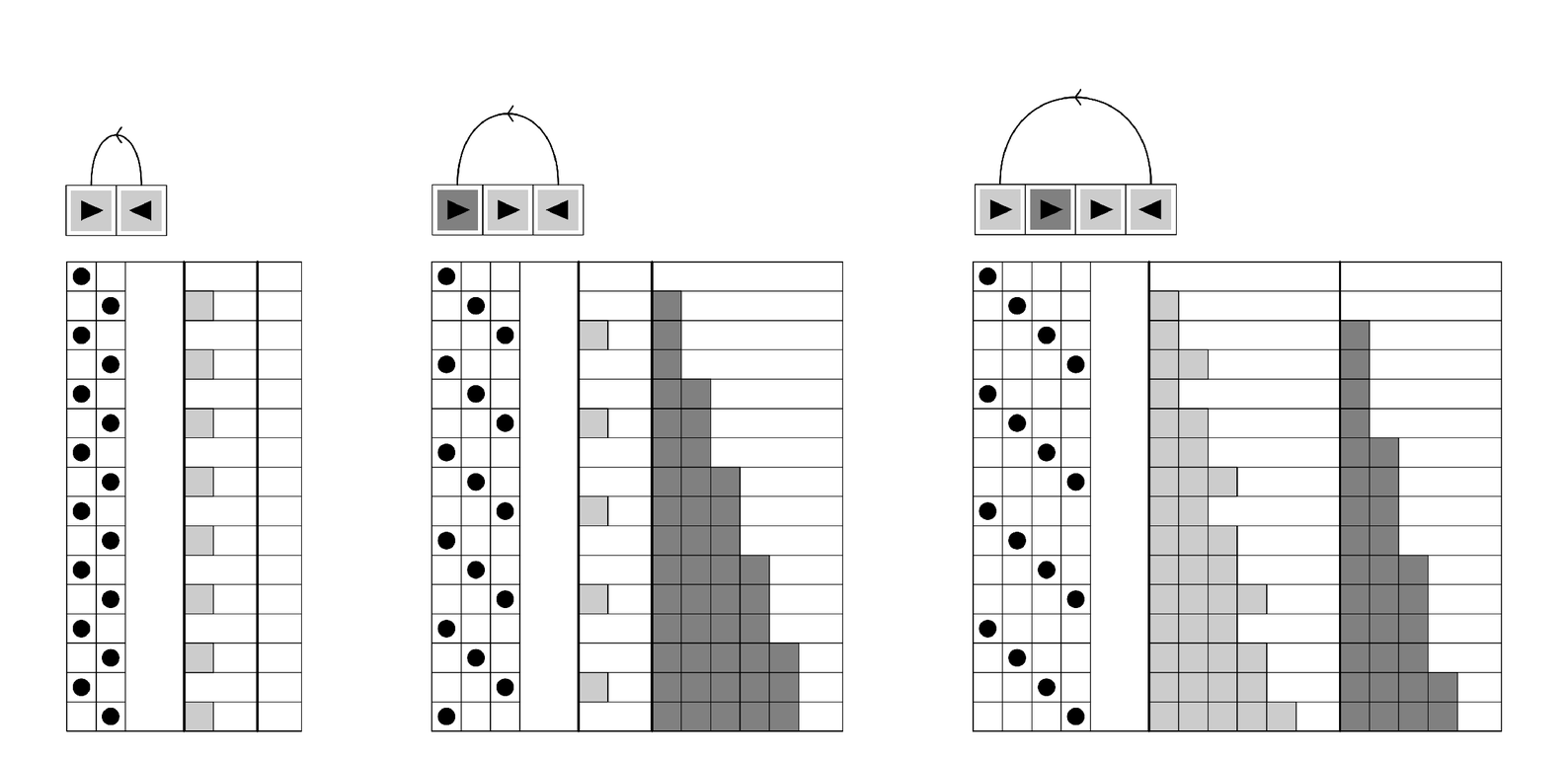
And with this setup, the pictures below show three very simple examples of register machines with two registers. The programs for each of the machines are given at the top, with ► representing an increment instruction, and ◄ a decrement-jump. The successive steps in the evolution of each machine are shown on successive lines down the page. The instruction being executed is indicated at each step by the position of the dot on the left, while the numbers in each of the two registers are indicated by the gray blocks on the right.
All the register machines shown start by executing the first instruction in their programs. And with the particular programs used here, the machines are then set up just to execute all the other instructions in their programs in turn, jumping back to the beginning of their programs whenever they reach the end.
Both registers in each machine are initially zero. And in the first machine, the first register alternates between 0 and 1, while the second remains zero. In the second machine, however, the first register again

Examples of simple register machines, set up to mimic the low-level operation of practical computers. The machines shown have two registers, whose values on successive steps are given on successive lines down the page. Each machine follows a fixed program given at the top. The program consists of a sequence of increment ► and decrement-jump ◄ instructions. Instructions that are shown as light gray boxes refer to the first register; those shown as dark gray boxes refer to the second one. On each line going down the page, the black dot on the left indicates which instruction in the program is being executed at the corresponding step. With the particular programs shown here, each machine just executes successive instructions in turn, jumping to the beginning again when it reaches the end of the program.